
Last time I showed you how to set up a windowed OpenGL ES 2 (GLES2) context on AmigaOS. Now lets draw something. This tutorial will show you how to use shaders to draw stuff (a simple triangle, in this case).
It closely follows a similar Warp3D Nova tutorial, and you’re welcome to compare the two.
NOTE: While this tutorial is for AmigaOS, the OpenGL code is cross-platform. However, on other platforms you’ll need to use setup code that platform, or a cross-platform library such as GLUT or EGL.
The Shader Based Graphics Pipeline
Modern Graphics Processing Units (GPUs) are based around programmable shaders. They take in data (vertices, textures, etc.), perform calculations, and output the results. Programmable shaders give developers great freedom over lighting and geometric models to use.
Two shaders are required: a vertex shader and a fragment shader (a.k.a., a pixel shader). These are connected into a pipeline as shown below:
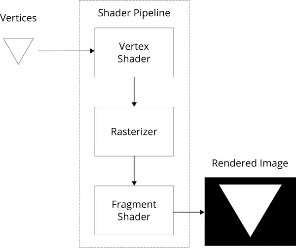
Here’s how the shader pipeline (above) renders our triangle:
- The vertex shader is executed once for each vertex in our triangle. It transforms those vertices to “clip” coordinates and possibly outputs other attributes too
- A rasterizer reads those positions and interpolates them to build a list of which pixels/fragments are being rendered to. The clip-coordinates are also transformed to screen coordinates
- Finally, the fragment shader is run once for every pixel (or fragment); it outputs the final colour for each pixel (and possibly a depth value too)
The end result is the rendered image.
Step 1: Refactor the Code
Our starting point is the code from the previous tutorial. So, create a copy of the previous tutorial’s code, and rename it.
Now let’s do a bit of refactoring. Source code is easier to understand if it’s divided into logical blocks and organised into separate files. For example, the code that creates and manages render contexts is a logical block. I transferred that to a new file called Context.c. Likewise, the code to open/close libraries was moved to Init.c, and the showErrorRequester() function was shifted to Util.c.
Refactoring code doesn’t relate directly to Warp3D Nova, so I’m going to skip over it. Try to do the refactoring yourself, and/or have a look at the final tutorial code, which can be downloaded at the end of this tutorial.
Step 2: The Shaders
As mentioned earlier, we need two shaders: vertex shader and a fragment shaders.
The Vertex Shader
Create a text file called “Simple2D.vert”. If you’re using CodeBench, double-click on “other files” in the project window, and create the new file. Here’s the shader code for Simple2D.vert:
#version 140

in vec2 vertPos;

out vec4 colour;

const vec4 white = vec4(1.0);

void main() {
    colour = white;
    gl_Position = vec4(vertPos, 0.0, 1.0);
}
Let’s go through this one section at a time. The “#version 140” statement at the top indicates that this shader is written in GLSL version 1.4.0.
The next two lines declare input and output variables:
in vec2 vertPos;

out vec4 colour;
So, the vertex shader takes a 2D vertex position as input, and outputs a 4 channel colour parameter. The colour output isn’t really needed right now, but it demonstrates passing parameters from the vertex shader through to the fragment shader.
The next line creates a constant for the colour white:
const vec4 white = vec4(1.0);
Colours have 4 channels, Red, Green, Blue, & Alpha (RGBA). The alpha channel stores how opaque a pixel is (0.0 being transparent, and 1.0 being 100% opaque). Vec4(1.0) is shorthand for a 4D vector where all values are 1.0, which is solid white.
The main() function is called for every vertex. The code simply sets the output colour to white, and copies the 2D position into gl_Position (which is a predefined output in GLSL 1.4).
void main() {
    colour = white;
    gl_Position = vec4(vertPos, 0.0, 1.0);
}
Vec4(vertPos, 0.0, 1.0) is the equivalent of vec4(vertPos.x, vertPos.y, 0.0, 1.0). This is needed because our input vector is 2D, whereas gl_Position is a 4D vector.
The Fragment Shader (Simple2D.frag)
The fragment shader code is as follows:
#version 140

in vec4 colour;

void main() {
    gl_FragColor = colour;
}
This simply takes the interpolated colour received from the vertex shader (via the rasterizer), and writes it to the output pixel (gl_FragColor).
Step 3: Compiling the Shaders
The shaders need to be compiled, and linked into a shader program before they can be used. Actually, first the shaders need to be loaded from the shader files.
Shader Compilation
There’s one thing we need to do before we can compile the shader: load the source-code from file. So let’s get started. Here’s the first part of the shaderLoad() function; the part that reads the shader from disk:
/** Loads and compiles a shader from a file.
 *
 * This will print any errors to the console.
 *
 * @param filename the shader's filename
 * @param shaderType the shader type (e.g., GL_VERTEX_SHADER)
 *
 * @return GLuint the shader's ID, or 0 if failed
 */
GLuint shaderLoad(const char *filename, GLenum shaderType) {
	FILE *file = fopen(filename, "r");
	if(!file) {
		fprintf(stderr, "Can't open file: %sn", filename);

		return 0;
	}

	size_t length = fileGetLength(file);

	// Alloc space for the file (plus NULL' termination)
	char *shaderSrc = (char*)malloc(length + 1);
	if(!shaderSrc) {
		fprintf(stderr, "Out of memory when reading file: %sn", filename);
		fclose(file);
		file = NULL;

		return 0;
	}

	fread(shaderSrc, length, 1, file);

	// NULL terminate the string
	shaderSrc[length] = '�';

	// Done with the file
	fclose(file);
	file = NULL;
This is generic C code, so I won’t go over it in detail. Basically, it opens the file, checks how long it is, and then reads its contents into a newly allocated block of memory called shaderSrc.
Next, the shader code is put into a new shader object:
	// Create the shader
	GLuint shader = glCreateShader(shaderType);
	glShaderSource(shader, 1, (const GLchar**)&shaderSrc, NULL);
Now it’s time to compile the code, and also check that compilation is successful:
	// Compile it
	glCompileShader(shader);
	GLint compileSucceeded = GL_FALSE;
	glGetShaderiv(shader, GL_COMPILE_STATUS, &compileSucceeded);
	if(!compileSucceeded) {
		// Compilation failed. Print error info
		fprintf(stderr, "Compilation of shader %s failed:n", filename);
		GLint logLength = 0;
		glGetShaderiv(shader, GL_INFO_LOG_LENGTH, &logLength);
		GLchar *errLog = malloc(logLength);
		if(errLog) {
			glGetShaderInfoLog(shader, logLength, &logLength, errLog);
			fprintf(stderr, "%sn", errLog);
			free(errLog);
		} else {
			fprintf(stderr, "Couldn't get shader log; out of memoryn");
		}

		glDeleteShader(shader);
		shader = 0;
	}
The glGetShaderInfoLog() function gets any compiler error messages. This is essential to solving any compilation issues.
Finally, it’s time to perform cleanup before returning the new shader:
	// Cleanup
	free(shaderSrc);
	shaderSrc = NULL;

	return shader;
}
Shader linking
Remember the shader pipeline mentioned earlier. Well, the vertex and fragment shaders need to be linked together to form a shader program. Shader programs are an entire shader pipeline linked up and ready to go.
First, load up the shaders:
/** Loads a vertex and fragment shader from disk and compiles (& links) them
 * into a shader program.
 *
 * This will print any errors to the console.
 *
 * @param vertFilename filename for the vertex shader
 * @param fragFilename the fragment shader's filename.
 *
 * @return GLuint the shader program's ID, or 0 if failed.
 */
GLuint shaderProgLoad(const char *vertFilename, const char *fragFilename) {
	GLuint vertShader = shaderLoad(vertFilename, GL_VERTEX_SHADER);
	if(!vertShader) {
		fprintf(stderr, "Couldn't load vertex shader: %sn", vertFilename);

		return 0;
	}

	GLuint fragShader = shaderLoad(fragFilename, GL_FRAGMENT_SHADER);
	if(!fragShader) {
		fprintf(stderr, "Couldn't load fragment shader: %sn", fragFilename);
		shaderDestroy(vertShader);
		vertShader = 0;

		return 0;
	}
Next, create the shader program, and link the shaders into it:
	GLuint shaderProg = glCreateProgram();
	if(shaderProg) {
		glAttachShader(shaderProg, vertShader);
		glAttachShader(shaderProg, fragShader);

		glLinkProgram(shaderProg);

		GLint linkingSucceeded = GL_FALSE;
		glGetProgramiv(shaderProg, GL_LINK_STATUS, &linkingSucceeded);
		if(!linkingSucceeded) {
			fprintf(stderr, "Linking shader failed (vert. shader: %s, frag. shader: %sn",
				vertFilename, fragFilename);
			GLint logLength = 0;
			glGetProgramiv(shaderProg, GL_INFO_LOG_LENGTH, &logLength);
			GLchar *errLog = malloc(logLength);
			if(errLog) {
				glGetProgramInfoLog(shaderProg, logLength, &logLength, errLog);
				fprintf(stderr, "%sn", errLog);
				free(errLog);
			} else {
				fprintf(stderr, "Couldn't get shader link log; out of memoryn");
			}
			glDeleteProgram(shaderProg);
			shaderProg = 0;
		}
	} else {
		fprintf(stderr, "Couldn't create shader programn");
	}
Finally, the shader objects can be deleted as we don’t need them any more:
	// Don't need these any more
	shaderDestroy(vertShader);
	shaderDestroy(fragShader);

	return shaderProg;
}
Activate the Shader
OpenGL won’t use the shader until you tell it to by calling glUseProgram(). So, insert the following code into the main() method (in GLTutorial2.c):
	// Load the shader program and set it for use
	GLuint shaderProg = shaderProgLoad("Simple2D.vert", "Simple2D.frag");
	if(!shaderProg) {
		// Error messages already displayed...
		retCode = 10;
		goto CLEANUP;
	}
	glUseProgram(shaderProg);
This loads the shaders (shaderProgLoad()), and activates them (glUseProgram(shaderProg)). It should be inserted between the rcCreate() code and the main loop.
Be sure to delete the shader program after the main loop with the following code:
	if(shaderProg) {
		shaderDestroy(shaderProg);
		shaderProg = 0;
	}
The shaderDestroy() function is listed in the next section below.
Cleanup Code
Before moving on, let’s take a quick look at the shader cleanup code. This should be executed when a shader or shader-program is no longer needed. First, here’s the code to delete a shader:
/** Destroys a shader.
 */
void shaderDestroy(GLuint shaderID) {
	glDeleteShader(shaderID);
}
Pretty simple, eh? We could simply call glDeleteShader() directly, but create our own function for API consistency (so we have matching create and destroy functions). The shader program delete code is equally straightforward:
/** Destroys a shader program.
 */
void shaderProgDestroy(GLuint shaderProg) {
	glDeleteProgram(shaderProg);
}
Step 4: Create the Vertex Array
We need to give OpenGL the coordinates to our triangle’s 3 vertices. These details are stored in the following vertex array:
	const float vertices[] = {
			 0.0f, -0.9f,
			 0.9f,  0.9f,
			-0.9f,  0.9f
		};
	GLsizei vertSize = sizeof(vertices[0]) * 2;
	GLsizei numVertices = sizeof(vertices) / vertSize;
These coordinates are in what’s called “clip” space. I don’t want to go into the nitty gritty of what clip space is; all you need to know right now is that the bottom left corner is at 2D coordinate (-1,-1), and (1,1) is the top right corner’s location. So the coordinates above draw a triangle that covers most of the screen/window. The coordinates are as follows:
- Vertex 1: (0.0, -0.9) is bottom centre
- Vertex 2: (0.9, 0.9) is top right
- Vertex 3: (-0.9, 0.9) is top left
Step 5: Render the Triangle
Now we can finally render the triangle. First, though, let’s clear the screen:
	// Clear the screen
	glClear(GL_COLOR_BUFFER_BIT);
Rendering is a two step process. First we tell OpenGL where to find the vertex data (and what format it’s in):
	// Set up the vertex array
	glVertexAttribPointer(0, 2, GL_FLOAT, GL_FALSE, 0, vertices);
	glEnableVertexAttribArray(0);
This code sets the pointer for the vertex position (vertex attribute 0, in this case) to point to our vertices, and tells OpenGL that the array contains tightly packed 2D vertices that are of type GL_FLOAT.
At this point we’ve given OpenGL the shaders to use and told it where to read the triangle’s vertices from. Everything is set up. Now, the triangle can (finally) be rendered:
	// Draw
	glDrawArrays(GL_TRIANGLES, 0, numVertices);
Put the code above into a drawScene() function; it’s more readable than putting it directly into the main loop. DrawScene() should be called every time the window needs to be redrawn. Here’s the updated window refresh code (in the main loop):
		if(refreshWindow) {
			// Render our scene...
			drawScene();


			// Swap the buffers, so that our newly rendered image is displayed
			rcSwapBuffers(renderContext);

			// All done
			refreshWindow = FALSE;
		}
The code above renders the scene (drawScene()), and then swaps the buffers to make it visible (rcSwapBuffers()). Congratulations, you rendered your first image!

Caveat: Vertex Arrays are Bad
Okay, they’re not exactly bad. However, they aren’t the fastest way of rendering and you really should be using Vertex Buffer Objects (VBOs). Vertex arrays are stored in main memory, whereas VBOs can be stored in VRAM where the GPU has very high speed access to them.
So, why did I just teach you how to use vertex arrays then? Because they’re easier and you have enough to learn already. VBOs require more steps to set up. I’ll cover those in a future tutorial.
Conclusion
You should now understand the basics of how to use shaders to render graphics using GLES2. Sure, it’s just one white triangle. However, computers are very good at repetitive tasks so this is easily extended to rendering thousands. In fact, why don’t you have a go? Try updating the tutorial code to render multiple triangles.
In the next tutorial we’ll add a splash of colour.
Download the complete tutorial code: GLTutorial2.lha
Got any questions or comments? Write them in the comments section below.